


XP Power übernimmt Fug Elektronik und Guth
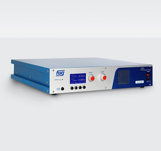
FuG Elektronik GmbH und Guth High Voltage GmbH sind jetzt Teil von XP Power, einem der weltweit führenden Entwickler und Hersteller von kritischen Stromversorgungslösungen für die Elektronikindustrie.
Standard Lösungen
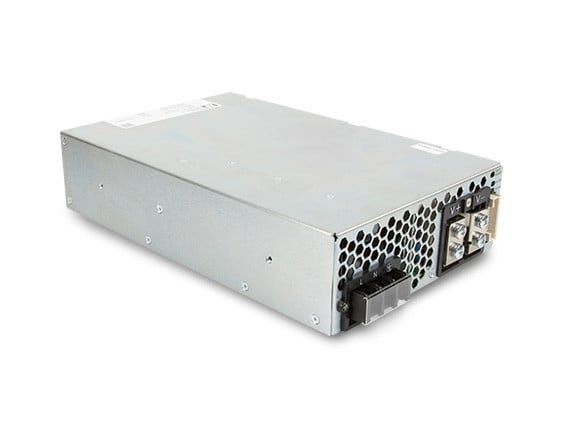
XP Power liefert hochpräzise, hochstabile Hochspannungsversorgungen für Anwendungen in Halbleiterfertigungsanlagen, der Medizintechnik und in der Industrie.
Durch die Akquisition von FuG und Guth können wir nunmehr Standardlösungen mit Ausgangsspannungen bis 300kV und Ausgangsleistungen bis 600kW anbieten. Damit erhalten Sie die außergewöhnliche Genauigkeit und Zuverlässigkeit, die für die Versorgung von Massenspektrometern, Elektronenstrahl-, Elektrostatik-, Kondensatorladung- und anderen Spezialanwendungen benötigen wird.

Kundenspezifische Lösungen
Unsere kundenspezifischen Stromversorgungslösungen bieten Ihnen die Genauigkeit, Stabilitäten und geringe Restwelligkeit der Ausgangsspannung, die Sie benötigen, um sicherzustellen, dass Ihre Anwendungen sicher funktionieren.
Wir können jetzt die Kenntnisse und Fertigkeiten der erfahrenen FuG- und Guth-Hochspannungsingenieure, Hardware-/Software-Entwickler und Facharbeiter nutzen, um Ihre Anforderungen besser zu verstehen und kundenspezifische Hochspannungslösungen zu entwickeln. Unsere Direktvertriebs- und technischen Support-Teams arbeiten mit Ihnen von der Entwicklungsphase über den gesamten Lebenszyklus Ihres Produkts eng zusammen.
Senden Sie uns eine E-Mail an fug-web-sales@xppower.com mit Ihrer individuellen Leistungsanfrage.

Karriere bei der XP Power Group, Deutschland
Wenn Sie Ihre Karriere in der Hochspannungstechnik an unseren Standorten in Schechen (bei Rosenheim) oder Salach (bei Göppingen) voranbringen möchten, bieten wir Ihnen hervorragende Möglichkeiten und die Chance, sich bei der XP Power Group in Deutschland zu entwickeln.